电容三点式振荡器 电容三点式振荡器是一种电子元件,也叫考毕兹振荡器,是自激振荡器的一种。由串联电容与电感回路及正反馈放大器组成,因振...
串联电路的谐振
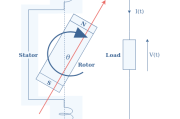
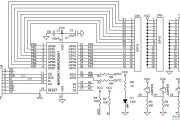
接线图
2023年07月21日 22:53 211
admin
- 谐振现象在自然界中是普遍存在的,电子学也有这种情况。
1. RLC 串联电路谐振的定义


- 即当激励电源的频率为 ω0 时,RLC 串联电路发生谐振。
2. RLC 串联谐振的特性与 Q 值描述
①谐振时电路呈电阻性,且阻值为阻抗的最小值


- 并不为 0,当 R 很小时,分电压可能很大,甚至远大于电源电压,造成电路损坏。但两分电压极性相反,对外电路呈现短路状态。故串联谐振也称为“电压谐振”。
- ②串联谐振电路中 Q 值- 品质因数
- 谐振期间,L,C 之间互相交换能量,该能量是在初始建立振荡时由电源提供的,其大小为:

- 而每振荡一次,电路消耗的能量为:

- 定义 Q 值:


- 其它表示式:

3.RLC 串联谐振的频率选择特性
- 以 UR 输出为例,输出与输入之比为:


- ω 越接近 ω0,输出值越高;而偏离ω0 的输出则被抑制。
定量描述选频特性时,要用同频带宽度 △f 来衡量:它等于峰值两边的 0.707 处所对应的频率之差:

相关文章
发表评论